 |
 |
 |
 |
 |
 |
 |
 |
 |
 |
 |
Core System Layouts
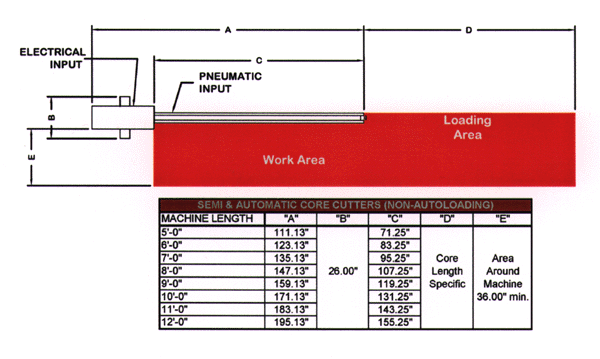
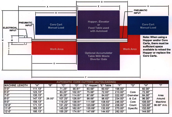
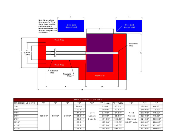
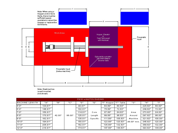
The space required for your core cutting system is dictated by the parent core length you use, the vendor parent core packaging, and the extent of automation you select. The layouts below provide a sense of the amount of space required. Your specific system layout will be dependent on the equipment you select and the constraints of your facility.
To get an estimate of the space required, use the chart and layout appropriate to the model of cutter you are considering. In the chart, look up the length “C” for the parent core you expect to be using. Read the values associated with that length to size the layout.
The layouts on this page are also available here as Adobe Acrobat (pdf) files. To download the latest free version of Adobe Acrobat follow the link below.

Universal Series Cutters
The models S210, A301, A400, A400t and P5xx dimensions are shown on the chart and layouts immediately below.
Basic Cutter with Manual Handling
Download an Adobe acrobat "pdf" version for better
printing here.
(Download Time: Approximately 15 seconds on a 56k modem)
Cutter showing Automation Options
Download an Adobe acrobat "pdf" version for better
printing here.
(Download Time: Approximately 1 minute on a 56k modem)
MDHS Series Cutters
The chart and layout for the MDHS series cutters is immediately below.
Download an Adobe acrobat "pdf" version for better
printing here.
(Download Time: Approximately 1 minute on a 56k modem)
P610 Core Cutters
The chart and layout for P610 Programmable Cutter based systems is immediately below.
Download an Adobe acrobat "pdf" version for better
printing here.
(Download Time: Approximately 1 minute on a 56k modem)